Shader programs
Keywords:
tutorial,
X3D,
world,
rendering
Author(s): Yvonne Jung
Date: 2007-02-05
Summary: This tutorial shows how to write a simple shader in X3D.
Shader program definition
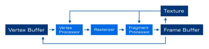
First an example of a simple Shape with a basic shader Appearance, which contains an ImageTexture, a ComposedShader and two ShaderPart nodes, is shown. GLSL- Shaders are written within a ShaderPart. The shader code can be either embedded within the X3D file or in another file containing only the shader program. There are three types of ShaderPart nodes: vertex, fragment and geometry. The latter is only supported on Shader Model 4.0/ Direct3D 10.0 hardware or later (e.g. NVidia GeForce 8800 graphics card). The program stages for the other two types are visualized in the following image (texture access for vertex shaders needs at least Shader Model 3.0 hardware).
Uniform parameters can be set via the dynamic field mechanism: For each uniform variable needed, a field or an exposedField with the same name and data type should be defined. This has to be done in the ComposedShader node. In order to define textures (uniform variables of any sampler type), an exposedField of type SFInt32 referring to the appropriate texture unit has to be defined (in case of the following example this is the first one, i.e. unit 0, because no MultiTexture is used).
When writing a geometry shader, there are three other fields for defining input and output primitive types as well as the maximum number of vertices to be generated in the shader: geometryInputType, geometryOutputType and geometryVerticesOut.
Note: Generic vertex attribute parameters are currently not supported. If they are needed (e.g.tangents), they can be encoded in the texCoord or color field of the geometry node.
Code: A basic shader appearance
	Shape {
		appearance Appearance {
			texture ImageTexture {
				url "testImage.jpg"
			}
			shaders ComposedShader {
				exposedField SFInt32 tex0    0
				exposedField SFVec3f diffuse .7 .7 .7

				parts [
					DEF vert ShaderPart {
						type "vertex"
						url "testShaderVP.glsl"
					}
					DEF fs ShaderPart {
						type "fragment"
						url "testShaderFP.glsl"
					}
				]
			}
		}
		geometry Sphere	{}
	}
If you want to use CG for your shader programs, you have to replace the ComposedShader node by a ProgramShader node with its language field set to "cg". Additionally the parts field has to be replaced by the programs field and the ShaderPart nodes by ShaderProgram nodes.
Example: Phong shader
This example shows, how a simple glsl shader implementation is done within X3D. For additionally demonstrating how to access a texture, the diffuse color is taken from an earth texture. In order to ensure the correct mapping between the X3D field defining the texture unit and the sampler uniform definition, both variables must have the same name, which - in case of our example - is earthTex. By the way, the same goes for all other uniform variables likewise.
Code: Uniform parameters
	Appearance {
		texture ImageTexture {
			url "earth.jpg"
		}
		shaders ComposedShader {
			exposedField SFInt32 earthTex 0
			exposedField SFFloat ambient  .2
			exposedField SFVec3f specular .7 .7 .7

			parts [
				# ...
			]
		}
	}
Vertex shader
In the vertex shader the incoming vertex position is transformed with the current modelview-projection matrix with the help of the ftransform function. After that all varying parameters, which are required by the subsequent fragment shader and interpolated across the primitive during rasterization (like gl_TexCoord and the user defined ones for normal, eye vector and light vector) are calculated.
Code:
	DEF vs ShaderPart {
		type "vertex"
			url "
			varying vec3 lightVec;
			varying vec3 eyeVec;
			varying vec3 normalVec;

			void main(void)
			{
				gl_Position = ftransform();

				gl_TexCoord[0] = gl_MultiTexCoord0;
				normalVec = gl_Normal;

				vec4 eyePos = gl_ModelViewMatrixInverse * vec4(0., 0., 0., 1.);
				eyeVec = eyePos.xyz - gl_Vertex.xyz;

				vec4 lightPos = gl_ModelViewMatrixInverse * vec4(gl_LightSource[0].position.xyz, 1.0);
				lightVec = lightPos.xyz - gl_Vertex.xyz;
			}
		"
	}
Pixel Shader
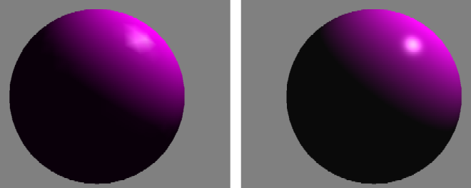
The fragment shader realizes the Blinn-Phong lighting model, without attenuation factor (the complete formula is depicted in the following image). After texture access all vectors are normalized and the final fragment color is calculated. A good introductory text to glsl shader programming is the so-called Orange Book. Another application domain for shader programming is imaging; in the files section you will find examples for both.

Code:
	DEF fs ShaderPart {
		type "fragment"
		url "
		uniform sampler2D earthTex;

		uniform vec3 specular;
		uniform float ambient;

		varying vec3 lightVec;
		varying vec3 eyeVec;
		varying vec3 normalVec;

		void main(void)
		{
			vec3 texCol = texture2D(earthTex, gl_TexCoord[0].st).rgb;

			lightVec = normalize(lightVec);
			eyeVec = normalize(eyeVec);
			normalVec = normalize(normalVec);
			vec3 halfVec = normalize( eyeVec + lightVec );

			float ndotl = max( dot( lightVec, normalVec ), 0.0 );
			float ndoth = (ndotl > 0.0) ? pow(max( dot( halfVec, normalVec ), 0.0 ), 128.) : 0.0;

			vec3 color = 0.2*ambient + ndotl*texCol + ndoth*specular;

			gl_FragColor = vec4(color, 1.0);
		}
		"
	}
Using HDR Images
Using hdr images within your shader is quite straightforward. Simply create a texture with your OpenEXR or Radiance image and set the internalFormat field to a floating point format like rgba16f as shown in the following code snippet, where a hdr cube texture is used. The texture look-up in your shader works just like already explained before, but additionally you should apply some kind of tone mapping before displaying the final color value. The field internalFormat can also be used in combination with ordinary ldr images in case you want to perform a texture look-up in your vertex shader e.g. for displacement mapping. Here you need "nearest" filtering, and your height map must internally be converted into floating point format by setting this field to something like luminance32f.
Code: Using an hdr image of type OpenEXR
	ImageCubeMapTexture {
		repeatS FALSE
		repeatT FALSE
		repeatR FALSE
		internalFormat "rgba16f"
		url "StageEnvCube.exr"
	}
Geometry Shader Extensions
Geometry shaders (an example is shown below, additionally you find a simple test in the files section) require to set some additional fields:
- geometryInputType defines the input primitive type for the geometry shader, possible values are "auto", "points", "lines", "triangles", "lines_adjacency", "line_strip_adjacency", "triangles_adjacency", "triangle_strip_adjacency";
- geometryOutputType defines the output primitive type for the geometry shader, possible values are "auto", "points", "lines", "line_strip", "triangles", "triangle_strip";
- geometryVerticesOut sets the maximum number of vertices to be generated by the geometry shader, which is important for performance.
Code:
	ComposedShader {
		geometryInputType  "points"
		geometryOutputType "triangle_strip"
		geometryVerticesOut 16

		exposedField SFInt32 dataFieldTex 0
		exposedField SFInt32 edgeTableTex 1
		exposedField SFInt32 triTableTex 2
		exposedField SFVec3f dataStep 0.02 0.02 0.04
		exposedField SFFloat isolevel 0.2
		#[...]

		parts [
			DEF vert ShaderPart {
				type "VERTEX"
				url "TestG80_VS.glsl"
			}
			DEF geo ShaderPart {
				type "GEOMETRY"
				url "TestG80_GS.glsl"
			}
			DEF frag ShaderPart {
				type "FRAGMENT"
				url "TestG80_FS.glsl"
			}
		]
	}
Comments
This tutorial has no comments.
Add a new comment
Due to excessive spamming we have disabled the comment functionality for tutorials. Please use our forum to post any questions.